
Introduction
This system utilizes the NE555 timer to produce a square wave signal. The NE555 timer IC works in an astable multivibrator, so the duty cycle of the square wave can be adjusted according to our needs by rotating a potentiometer. The output of the timer IC is connected to CD-4017-decade counter. The traffic lights are connected to the decade counter output in a sophisticated way. In this tutorial, we are going to discuss the step by step process to make a NE55 timer IC and CD-4017 based 4-way traffic light system.
The maximum duration of 4 and a half minutes should be possible with perfect valued components; however, due to the 220µF timing capacitor’s gradual charge leak, this is usually stretched to approximately ten minutes. All electrolytic capacitors have this issue, some leak more than others. Furthermore, electrolytic capacitors’ real values can differ by up to ±30% from their rated values. In this tutorial you are going to demonstrate how to implement the NE555 timer IC based adjustable Timer IC.
Use Cases
- To create oscillators, pulse generators, or delay circuits.
- In applications such as digital clocks, LED flashers, or interval timers
- Automation and control system for lighting control, irrigation systems, or industrial machinery
Components Required
- NE555 Timer IC
- Potentiometer
- Resistors
- Capacitors
- LED Lights
- Buzzer
- Breadboard or Veroboard (Optional: PCB)
- Connecting wires
- 5V power Supply
Circuit Diagram
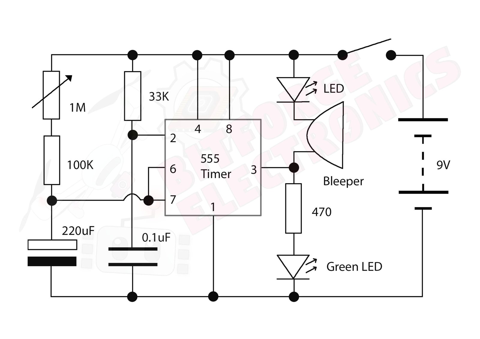
Instructions
The hardware setup should be made according to the diagrams. To vary the maximum and minimum time duration for the timer, the capacitor value and the resistor values can be adjusted. You should use 1/2.2 uF capacitor instead of 0.1uF capacitor. This is to hold the trigger pin much longer period time to hold it as negative when IC powers up.


